FFP EVALUATION QUIZ
HERE’S THE ANSWERS
Qu 1 FFP Principles
API RP 579 assessments cannot give very accurate results when which one of the following is present in the component being assessed?
a) Welds
b) Dynamic stresses
c) Principal stresses
d) Stresses above the material’s yield point
Ans (b). Most FFP assessments cannot deal with dynamic stresses or crack-growth states. All the other options are covered by API RP 579
Qu 2: Vessel stresses
Where is the highest stress located in a vessel hemispherical head under internal pressure?
a) In the hoop plane
b) In the circumferential plane
c) In the knuckle area
d) None of the above
Ans (d) as it is equal in all meridional directions. Option (c) cannot be correct as a hemispherical head has no ‘knuckle’.
Qu 3: Flange stresses
Two mating raised face (RF) flanges have been over-machined to remove corrosion and their flange thickness dimensions are now outside code (ASME B16.5). They are now joined and the bolts over-tightened. What kind of stress predominates in the flanges and could lead to leakage or flange failure?
a) Torsional stresses >90% yield
b) Compressive
c) Bending
d) Buckling
Ans (c). There is no effective torsion. There will be compressive stress but the main one is bending under flange ‘rotation’. Shear stress may be another valid answer hence it is not given as an answer option.
Qu 4: Vessel FFP assessment
FFP assessments on corroded pressure vessels with nozzles can be very inaccurate when the vessel has not required PWHT and the corroded area for assessment is located?
a) Inside a nozzle’s limit of reinforcement
b) On a shell circumferential (SAW) weld
c) Outside a nozzle’s limit of reinforcement
d) Within 5 x material thickness of a shell longitudinal weld (GTAW [TIG] root with SMAW fill)
Ans (a). Not accurate within nozzle reinforcement limits. SAW weld is OK as not really a structural discontinuity. Also SMAW weld with GTAW root is OK – a proven WPS for pressure vessel and no reason why it should cause stress concentration.
Qu 5: Stress in pipework
A simply supported thin walled pipe is loaded uniformally along its length and contains an internal pressure. Which of these statements is untrue?
a) Stress in the pipe is assumed to be 2-dimensional
b) Tensile stress increases with increasing distance from the neutral axis
c) Bending stress is always larger than the pressure stress
d) The second moment of area ‘inertia’ I is constant along the length of the pipe
Ans (c) is the only sensible answer; the relationship depends on the pipe diameter and its internal pressure. Stress is assumed 2-D in thin walled pipes. I is constant along the length as it is a function of the pipe cross-sectional shape.
5-MINUTE COACHING
THE PRINCIPLE OF API 579 FFP STUDIES
Fitness-for-purpose (FFP) assessments (termed fitness-for-service (FFS) assessments in the USA) play a prominent role in the world of in-service inspection. Their most common use is for pressurised equipment and structural components where integrity is an important issue.
FFP ASSESSMENTS ¾ WHAT ARE THEY?
A FFP assessment is a set of calculations performed on a component that contains some kind of feature that is suspected to affect its integrity. It is pure calculation so, although the calculation routines are based on engineering reality (supposedly), it is a purely theoretical exercise rather than a practical one. The whole concept of FFP assessment carries with it a specific set of terminology, which, whilst perfectly consistent in itself, does not necessarily coincide with common, or even general engineering usage, of the words ¾ so it can be a bit confusing
FFP ASSESSMENTS ¾ THE APPROACH
The central concept of a FFP assessment is that it looks at the effect on FFP of an existing flaw. It tries to predict how and when the flaw will cause the component to fail ¾ and it does this by considering the various failure mechanisms (ways of failure) that could happen. There is a graded approach to assessment with three possible levels of investigation. The higher the level of investigation, the more the failure mechanisms are considered in depth, and the greater the mathematical rigour that is used.
FFP approach ¾ two key points
A key point of the approach of a FFP assessment is its relationship to code compliance e.g. the compliance of a pressure vessel with the construction requirements of ASME VIII, EN 13445 or another of the recognised published technical standards. Note two key points:
- Most FFP assessments are done on components that are outside code compliance limits in some way i.e. they are rejectable under the code. This means that FFP assessments are, fundamentally, based on different acceptance criteria than design codes. This introduces the apparent paradox of there being more than one valid set of flaw acceptance criteria for the same engineering component.
- The defect acceptance criteria given in technical codes (ASME VIII, EN 13445 etc) are not indicators of FFP. They are best thought of indicative levels that can be reached if all the code requirements on materials, QA/QC, design features etc. are met
The inference here is that the existence of out-of-code flaws (using the FFP assessment term) does not mean that a component is not fit for purpose or unsafe. It means, merely that it does not meet the full requirements of the code, some of which may be FFP-related but many of which are chosen for practical reason, or simply convenience. All of this reinforces the need for in-service inspectors to appreciate the basic principles of FFP assessment and recognise the different approach to that of simple code compliance.
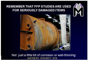
See our short slide presentation covering this topic


